The screen buffer
In the last post, we explored the display layout. This time, we’ll look at the screen buffer and how graphics are stored in it.
Today’s post isn’t about the game itself, but I felt that it was important to cover some of the technical details of how the Atari ST’s screen buffer works for those who don’t have prior knowledge.
I’m assuming you already have a basic understanding of binary arithmetic. Otherwise, this post might be a bit hard to follow. The obligatory Wikipedia link may be of help here.
Display modes
The Atari ST has a few different display modes, but the one used for this game (like most games on the ST) is called low-res mode, with a resolution of 320x200 pixels and 16 simultaneous colors from a palette of 512 possible colors.
Palette
The palette is a set of colors that can be used in the display. Each color in the palette is defined by a combination of red, green, and blue (RGB) values.
Because the Atari ST’s palette allows for 512 different colors, a color consists of 3 bits for each primary color (R, G and B), with a total of 9 bits (2^9 = 512).
Each palette entry is stored as a 16-bit word in memory. The bits for each color are arranged as follows:
Bit 15 14 13 12 11 10 09 08 07 06 05 04 03 02 01 00
     -  -  -  -  -  r  r  r  -  g  g  g  -  b  b  b
On the Atari STE, there’s an extra bit per primary color, which allows for 4096 colors, but this game targets the Atari ST, so we won’t go into that here.
For example, a palette could look like this:

This results in the following hexadecimal values for the palette entries:
     0    1    2    3    4    5    6    7    8    9   10   11   12   13   14   15
$ 0000 0211 0631 0771 0472 0143 0224 0347 0267 0134 0333 0324 0635 0442 0667 0777
Memory layout
Because low-res supports 16 colors, each pixel is represented by 4 bits (since 2^4 = 16).
Each bit of a pixel color is stored separately in a bitplane. Because there are 4 bits per pixel, there are 4 bitplanes. Conceptually, you can think of the bitplanes as layers that together form the final image. Each bitplane contributes one bit to the color of each pixel, and the combination of these bits determines the final color displayed on the screen.

However, the bitplanes are stored in the display buffer in an interleaved manner, divided into 16-bit words. After the first 16-bit word of bitplane 0, the first 16-bit word of bitplane 1 follows, then bitplane 2, and finally bitplane 3. After that, the second 16-bit word of bitplane 0 follows, and so on.

This means that the memory layout can be represented like below, where the first pixel on the display (at coordinates X=0, Y=0) is represented by the first 4 bits of the first 16-bit word in each bitplane, and so on for the rest of the pixels.
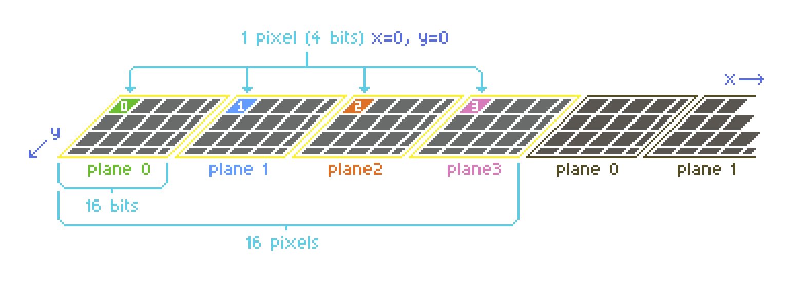
In the diagram above, you can see where the bits of the first pixel (located at x=0, y=0, which is the top-left of the screen) are located in the bitplanes.
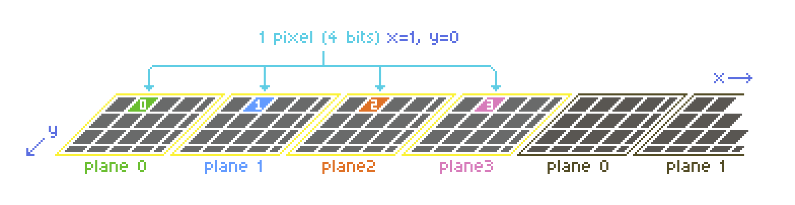
To further illustrate this, let’s look at the second pixel (located at x=1, y=0):
Example
A fragment of a screen buffer with some example pixels drawn on it could look like this:
          Bitplane 0       Bitplane 1       Bitplane 2       Bitplane 3
y=0 ---------------- ---------------- ---------------- ----------------
y=1 --111----------- ---------------- --111----------- --111-----------
y=2 -1---1---------- -1---1---------- ---------------- ----------------
y=3 -11111---------- -1---1---------- -11111---------- ----------------
y=4 -1---1---------- -1---1---------- ---------------- ----------------
y=5 -1---1---------- -1---1---------- ---------------- ----------------
y=6 ---------------- ---------------- ---------------- ----------------
Note that I’ve replaced the 0s with dashes for better readability
To find the color of a pixel, you would take the corresponding bits from each bitplane and combine them. For example, for the pixel at the exact center of the A shape (x=3, y=3), you’d take:
- Bit
4from bitplane0on rowy=3(which is1) - Bit
4from bitplane1on rowy=3(which is0) - Bit
4from bitplane2on rowy=3(which is1) - Bit
4from bitplane3on rowy=3(which is0)
This gives you a binary value of 1010, which translates to 10 in decimal, meaning that the pixel gets the color at index 10 of the palette.
Finally, to get a sense of how this is stored in memory, the example bitmap expressed in hexadecimal values looks like this:
$ 0000 0000 0000 0000
$ 3800 0000 3800 3800
$ 4400 4400 0000 0000
$ 7c00 4400 7c00 0000
$ 4400 4400 0000 0000
$ 4400 4400 0000 0000
$ 0000 0000 0000 0000
Consequences
The bitplane layout makes graphics programming a bit more complex, but it also allows for some interesting techniques, such as using the bitplanes to create special effects by manipulating them separately. For instance, you can draw graphics to only a few of the bitplanes instead of all four, to save CPU time, at the cost of having a limited number of colors for those graphics.
Up next
Continue reading with the next post: Sync scrolling