Sync scrolling
As you may know, the Atari ST (unlike the STE) officially doesn’t support hardware scrolling. In this post, I’m going to talk about a demoscene technique that allows an ST to achieve basic hardware scrolling regardless of that restriction. This technique is called sync scrolling.
In case you’re wondering: sync scrolling refers to the fact that it is implemented using beam synchronization techniques, which I’ll explain later.
Dyno wrote this great Atari ST Fullscreen demos history post on his site, which I urge you to read first because it also touches on the topic of sync scrolling and how it evolved over time.
Before I went on to use sync scrolling, I had been using a rather narrow playfield (much like Xenon did) to be able to maintain an acceptable framerate. But I kept thinking that it could be done better. I wanted a bigger playfield while spending fewer CPU cycles drawing it at the same time. I knew about sync scrolling from back in the day, when quite a few demos used the technique. So, I figured I could try to use sync scrolling to achieve that goal by not having to redraw the entire screen each cycle.
Hardware scrolling
Before we dive into sync scrolling, let’s first talk about hardware scrolling. Hardware scrolling in its simplest form means that the memory address where video hardware starts reading graphics from can be adjusted with a sufficient degree of precision to achieve smooth scrolling in at least one direction. This means that there is no actual moving of graphics in RAM involved in hardware scrolling.
This is my own definition of hardware scrolling. I’m sure there are alternative ones, but this definition suits our needs in this context.
Sync scrolling
So, we’ve already established that sync scrolling is a form of hardware scrolling. However, sync scrolling is a bit more restricted than traditional hardware scrolling.
Although the video address can be changed on the ST, it can only be changed in steps of 256 bytes, which results in 8-line granularity. This is because a scanline on the ST is always 160 bytes long and 8 * 160 = 1280 is the first number that is a multiple of 256. For smooth scrolling at a reasonable pace, such granularity is not sufficient because scrolling the screen by 8 lines each cycle is way too fast for most purposes. With sync scrolling on the ST we get vertical scrolling with 1-scanline precision and horizontal scrolling with 16-pixel precision. For this game, which scrolls vertically only, the horizontal precision is of no concern.
There’s also a technique that allows for 4-pixel horizontal precision, but sadly, it is not compatible with all ST(E) models and wakestates. I’ll refer to wakestates later in this post.
Besides changing the video address, some hardware platforms (like the STE or the Commodore Amiga) provide additional features, such as 1-pixel horizontal offset precision and configurable line lengths (allowing for virtual screens with horizontal screen wrapping), but that is not the case for sync scrolling on the ST.
With this knowledge, I wanted to see if I could implement sync scrolling in my game. I posted a question on atari-forum.com, asking what the best sync scroll routine was. Unsurprisingly, Troed (member of the aptly named demoscene group SYNC) was quick to reply and offer his help. For those who don’t know him, Troed is famous for his knowledge of Atari ST video synchronization tricks, and he has also released very impressive demos such as Closure, taking the concept of implementing effects previously thought impossible on an ST to an extreme.
After a few weeks of hard work and exchanging ideas and questions with Troed, I finally managed to get sync scrolling working in my game.
There were some rough edges to the sync scroll routines that had me puzzled a few times, but Troed was always there to help me out.
Further below, I will explain how I implemented sync scrolling in the game, but first, let’s investigate how sync scrolling actually works.
So how does it work?
Technically, sync scrolling works by tricking the GLUE chip into generating lines of various lengths, which in turn causes the MMU to read more or less graphics memory for those lines. This must be done before the point where graphics start being read (i.e., somewhere in the upper border). We’ll call the amount of graphics being read for a scanline line length from now on. Changing line lengths causes the graphics for the remaining scanlines to be shifted.
If you want to know more about the timing characteristics of the state machines inside the GLUE and Shifter chips, check out this excellent article.
The scanline length manipulation is achieved by switching between monochrome, 50Hz, and 60Hz modes at exactly timed moments during the scanline.
The change of line length causes the graphics for the remaining scanlines to be shifted accordingly. This, by itself, however, is not sufficient to achieve the granularity we need because only twelve different line lengths can be achieved.
But by repeating this process during several consecutive scanlines, several different line lengths can be combined to achieve every total graphics offset required for a 2-byte granularity.
A two-byte video address granularity in practice means a granularity of 16 pixels because of the way video memory is laid out using bitplanes.
Finding the correct combination of line lengths to achieve the desired total graphics offset is not trivial. Fortunately, Troed has created the synctable tool which allows us to generate a table of line length combinations that suits our needs (vertical scrolling with 1-scanline precision in our case).
Limitations
One effect of using sync lines is that graphics on those lines will look distorted. This problem can be solved by blanking the sync lines by setting the palette to all-black during the lines. However, the result is that there are a few fewer scanlines available for display.
Fortunately, this can be mitigated by using an overscan demoscene technique (in particular, opening the upper and/or lower borders) to regain and even extend the number of scanlines that display graphics.
The following diagram illustrates how the top border can be used to regain scanlines for graphics when using sync scrolling.
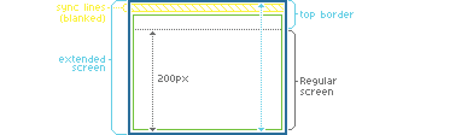
However, I will ignore this technique for the remainder of this post to keep things relatively simple.
Another aspect to keep in mind is that when the sync lines are active, timing must be fully predictable. This means that no interrupts must occur. This rules out the use of timers as well. So for example, music that uses timers to achieve SID sound effects cannot be used.
Finally, the timing of the sync lines depends on the actual hardware. As explained in the article mentioned above, there are different possible wakestates across hardware and across boots. A different wakestate often means that timings are different as well, so the code needs to compensate for this. The hardware dependency also means that sync scrolling will not work on non-compatible hardware, such as the Mega STE (running at 16 MHz and having a cache), the TT or the Falcon. Also, accelerated hardware will probably not work because of different timings. Fortunately, the regular STE is supported.
Implementation
Let’s dive into some of the details of how I implemented sync scrolling in the game.
This section is rather technical, so feel free to skip it if you’re not interested in the details.
As I described in the Technical design post, I’m using two libraries to implement sync scrolling:
- Wakestate detector
- Used to properly initialize the wakestate for the actual hardware.
- Sync scrolling library
- Contains the actual sync logic.
Basically, I’m using these libraries to set the video address with 2-byte granularity synchronized to each VBL1. For this to work, a bit of setup is required, which I’ll explain below.
The Sync scrolling library expects the following:
- A table of line length combinations for each possible scroll offset.
- A video address with
256byte granularity. - A scroll offset in bytes to further adjust the video address.
Once we have initialized the Sync scroll library with the table, we can use the following flow to handle sync scrolling during each frame:
sequenceDiagram
    autonumber
    activate Main loop
    Main loop->>Main loop: Update video memory
    Main loop->>+Vsync: Call
    Vsync->>Vsync: Wait for sync line routines to complete
    Vsync->>Vsync: Set up video address + scroll offset
    Vsync->>VBL: Wait for VBL
    Main loop->>+VBL: VBL interrupt
    VBL->>VBL: Set up Timer A
    VBL->>VBL: Blank out palette
    VBL->>-Vsync: Confirm VBL
    Vsync-->>-Main loop: Return
    deactivate Main loop
    Main loop->>+Timer A: Timer A interrupt
    Timer A->>Timer A: Wait for MMU to start reading graphics
    Timer A->>Timer A: Sync lock
    Timer A->>Timer A: Wait (n) cycles
    Timer A->>Timer A: Execute sync line routines
    Timer A->>-Timer A: Restore palette
To elaborate on each step in the flow above:
- The main loop updates video memory for the current frame. It may also perform other logic, such as updating the positions of sprites, checking for collisions, etc.
- The main loop calls the Vsync routine before continuing to process the next frame.
- The Vsync routine waits for the sync line routines to complete, if they haven’t already. This is important because the sync line routines must only be set up for the next frame, not the current.
- The Vsync routine sets up the video address and scroll offset in the Sync scrolling library for the next frame.
- The Vsync routine waits for the next VBL interrupt to occur.
- The VBL interrupt occurs.
- The VBL interrupt handler sets up Timer A to occur right before the moment when the MMU starts reading graphics. Using a timer saves CPU cycles in contrast to waiting in a loop.
- The VBL interrupt handler blanks out the palette to hide the sync lines.
- The VBL interrupt handler confirms the VBL to the Vsync routine by setting a flag.
- The Vsync routine confirms the VBL to the game loop by returning the call.
- The Timer A interrupt occurs.
- The Timer A interrupt handler waits for the MMU to start reading graphics.
- The Timer A interrupt handler performs a sync lock to ensure that an exact number of cycles has passed since the MMU started reading graphics.
- The Timer A interrupt handler waits for a specific number of CPU cycles to reach the exact moment when the sync line routines need to be executed.
- The Timer A interrupt handler executes the sync line routines.
- The Timer A interrupt handler restores the palette to make the graphics visible again.
The sync line combination table
Before we can initialize the Sync scroll library, we need to generate the line length combination table that it needs. This can be done by running the synctable tool with VERTICAL160 set to true (to indicate our interest in vertical scrolling only).
./Synctables
Calculating 1 lines of 12 combinations
Press Enter to increase number of lines, ESC+Enter to stop searching
Total searchspace: 12 calculations
Evaluating combos
Position 160 found, 127 combos missing, 8% searched
[...]
Position 206 found, 116 combos missing, 100% searched
Calculating 2 lines of 12 combinations
Press Enter to increase number of lines, ESC+Enter to stop searching
Total searchspace: 144 calculations
Evaluating combos
Position 64 found, 127 combos missing, 0% searched
[...]
Position 156 found, 79 combos missing, 100% searched
Calculating 3 lines of 12 combinations
Press Enter to increase number of lines, ESC+Enter to stop searching
Total searchspace: 1728 calculations
Evaluating combos
Position 224 found, 127 combos missing, 0% searched
[...]
Position 46 found, 22 combos missing, 90% searched
Vertical scroll possible, offset: 4
[...]
The tool then shows the following generated assembly code, which is intended to be included in the codebase:
*********************************************
*  Sync scroll table creator by Troed/SYNC  *
*  12 line lengths used                     *
*********************************************
* Columns as indexes into line-rout table. Last value is 256 byte offset
_linsrc: dc.l _s160,_s162,_s230,_s184,_s204,_s0,_s54,_s56,_s80,_s158,_s186,_s206
_synctab:
    dc.b 5,5,5,0        ; 0 (0)
    dc.b 2,2,6,2        ; 2 (514)
    dc.b 2,2,7,2        ; 4 (516)
    dc.b 5,7,11,1       ; 6 (262)
    dc.b 3,5,8,1        ; 8 (264)
    dc.b 0,4,9,2        ; 10 (522)
    dc.b 0,0,4,2        ; 12 (524)
    dc.b 0,0,11,2       ; 14 (526)
    dc.b 0,1,11,2       ; 16 (528)
    dc.b 0,3,10,2       ; 18 (530)
    dc.b 0,10,10,2      ; 20 (532)
    dc.b 1,10,10,2      ; 22 (534)
    dc.b 0,0,0,0        ; 24 not found
    dc.b 0,0,0,0        ; 26 not found
    dc.b 2,2,8,2        ; 28 (540)
    dc.b 2,5,7,1        ; 30 (286)
    dc.b 0,0,0,0        ; 32 not found
    dc.b 2,9,9,2        ; 34 (546)
    dc.b 0,2,9,2        ; 36 (548)
    dc.b 0,0,2,2        ; 38 (550)
    dc.b 0,1,2,2        ; 40 (552)

    ; ...for brevity, some rows are omitted...

    dc.b 0,5,8,0        ; 240 (240)
    dc.b 1,5,8,0        ; 242 (242)
    dc.b 3,9,9,1        ; 244 (500)
    dc.b 0,3,9,1        ; 246 (502)
    dc.b 0,0,3,1        ; 248 (504)
    dc.b 0,0,10,1       ; 250 (506)
    dc.b 0,1,10,1       ; 252 (508)
    dc.b 1,1,10,1       ; 254 (510)
It concludes with the following message:
3 lines needed for the sync scroll
Understanding the synctable tool output
There are a few takeaways from the output of the synctable tool:
- The
_linsrctable contains pointers to the sync line routines that the entries in_synctabcan choose from. -
The
_synctabtable contains the line length combinations for each possible scroll offset in the following format:dc.b L1[,L2..],O256 ; B (TO)where:
L1,L2, etc. are the line routine selection in the_linsrctable.O256is the multiple of256that we need to subtract from the video address.Bis the desired number of bytes that the row aims to represent as a combination of line lengths. If the row contains all zeros, it means that there is no line length combination possible for the corresponding value.TOis the total offset in bytes that this line length combination achieves. The final number indicates the number of 256 byte steps the video memory address has to be subtracted to reach the value ofB.
-
The
3 lines needed for the sync scrollmessage.This can be observed in the
_synctabtable rows, which contain 4 values, one for each of the3entries and one for the 256 byte offset. -
The
Vertical scroll possible, offset: 4message.It means that the graphics stored in memory should be offset by
4bytes relative to the actual video address. This may seem strange, but it allows the offsets in the_synctabtable to align correctly to obtain the desired offsets. If this offset was not applied, some of the scroll offsets that we need would align with rows in the_synctabtable that have no possible line-length combination (as indicated bynot found).
The following example shows how the Sync scrolling library calculates the effective video address to set in hardware and select the correct sync line routines to use to achieve the desired scroll offset that is fed into the Sync scrolling library.
Let’s say we want to offset the screen by 5 scanlines.
- The offset in bytes is
5 * 160 = 800bytes. - We add the graphics offset of
4bytes that the synctable tool advised us to apply, which gives us a total offset of804bytes. - We use the regular way of setting the video memory address as close as we can get, by rounding down the offset to the nearest multiple of
256which is768. - The remainder is
36which is what we use to accomplish the sync scroll. - Looking up
36in_synctab, we see that we need to use the line length combinations0,2and9(corresponding to line lengths of160,230and158bytes respectively), and then subtract2 * 256 = 512bytes from the video memory address. - The scroll offset can be verified by summing these offsets:
160 + 230 + 158 - 512 = 36.
Initialization
Now that we have the line length combination table, we can initialize the Sync scroll library.
First, a call to the Wakestate detect library needs to be made, so we can properly initialize the wakestate in the Sync scroll library.
    ; Wait for vertical blank (code omitted for brevity)
    ; ...

    jsr     _detect_ws
Next, a call to the Sync scroll library needs to be made to properly initialize the wakestate.
jsr _ws_patch
And finally, to further set up the sync scroll library:
jsr _ssinit
Display cycle
Now that the Sync scrolling library is initialized, let’s take a look at what needs to happen every display cycle to make sync scrolling work.
We’ll need the video address (with 256 byte granularity) and the scroll offset. These must be calculated each screen refresh based on the current scroll position of the game.
Let’s see some code that illustrates how the Vsync routine, the VBL handler and the Timer A handler can be implemented to achieve sync scrolling.
The code shown here is not the actual code used in the game but rather a simplified version that is intended to illustrate the concepts. I have not tested it as such, so there may be some errors in it. Please let me know in the comments below if you find any issues.
First, there’s the Vsync routine.
;----------------------------------------------------------------------------------------------
; Waits for the next VBL interrupt to occur.
;----------------------------------------------------------------------------------------------
vsync:

.waitLines:
        tst.b   lineRoutsFinished               ; Wait for the line routs to complete
        beq.s   .waitLines                      ; if they haven't finished yet.

        ; Update the sync-scroll.

        move.l  videoBase,_hscrladr
        move.l  scrollOffset,d0
        add.l   #4,d0                           ; Add the graphics offset (as advised
                                                ; by the sync table tool).
        move.l  d0,_hscrloff

        jsr     _setscr                         ; This routine updates the shifter
                                                ; base address and line routs.
.waitVbl:
        tst.b   vblSyncFlag
        beq.s   .waitVbl

        clr.b   vblSyncFlag                     ; Clear the VBL flag for the next vsync call.

        rts
Next, there’s the VBL handler.
;----------------------------------------------------------------------------------------------
; VBL interrupt handler.
;----------------------------------------------------------------------------------------------
vbl:    move.l  a0,-(sp)                        ; Save register.

        clr.b   lineRoutsFinished

        ; Set up timer A for sync-scroll.

        clr.b   $fffffa19.w                     ; Stop Timer A.
        move.l  #syncScroll_timerA,$134.w       ; Set Timer A handler.

        move.b  #57,$fffffa1f.w                 ; Set Timer A counter. This value may need
                                                ; adjustment for optimal timing.
        move.b  #6,$fffffa19.w                  ; Start Timer A with chosen prescaler.

        ; Clear the palette to hide the distortion that will be caused by the line routs.

        lea.l   $ffff8240.w,a0

        .rept 16/2
        clr.l   (a0)+
        .endr

        move.b   #1,vblSyncFlag

        move.l   (sp)+,a0                       ; Restore register.

        rte
And then the Timer A handler.
;----------------------------------------------------------------------------------------------
; Timer A interrupt handler for sync-scroll.
;----------------------------------------------------------------------------------------------
; This handler should fire right before the scanline where the shifter starts reading graphics.
; - Sync-locks to the first graphics scanline and calls sync-scroll line routs at the right
;    cycle to apply the offset that was configured using _hscrloff and the _setscr call.
; - Waits for the end of the graphics on the current line.
; - Restores the palette.
;----------------------------------------------------------------------------------------------
timerA: move.w  #$2700,sr                       ; Prevent interrupts.
        clr.b   $fffffa19.w                     ; Stop Timer A.

        movem.l d0/a0-a1,-(sp)                  ; Save registers.

        ; Prepare registers for line rout calls.

        lea.l   $ffff820a.w,a0
        lea.l   $ffff8260.w,a1
        moveq.l #0,d0

.syncLock:
        move.b  $ffff8209.w,d0                  ; Wait for video address to start changing.
        cmp.b   $ffff8209.w,d0
        beq.s   .syncLock

        ; The MMU has started reading graphics at this point. The number of already processed
        ; bytes varies slightly.
        ; D0 contains the number of processed graphics bytes. We can use the following trick
        ; to wait for the inverse amount of cycles to compensate for this variation.

        move.b  $ffff8209.w,d0                  ; Read the number of processed bytes.
        not.b   d0
        lsr.w   d0,d0                           ; This instruction takes more cycles the larger
                                                ; the value is.

        ; We're sync-locked right now, which means that the number of cycles passed since the
        ; beginning of the scanline is stable. The cycle count on the scanline should be exactly
        ; 200 at this point.

        ; Delay for 276 cycles.
        .rept 276/4
        nop
        .endr

        ; The jumps below are calls to sync lines 1-3. The addresses will be overwritten
        ; dynamically by _setscr. The first line rout should start at cycle 504 on the scanline
        ; but since the jsr takes 20 cycles by itself, we should be exactly at cycle 484 right
        ; now.

        ; Calls to the sync line routs. They expect #$ffff820a in a0, #$ffff8260 in a1 and #0 in
        ; d0. Each jsr takes 20 cycles by itself.

_jvar0: jsr     _s230
_jvar1: jsr     _s230
_jvar2: jsr     _s230
        jsr     _s204                          ; Finish with an extra stabilizer.

        ; The screen should now be offset according to _hscrloff.

        move.b  #1,lineRoutsFinished

        ; Delay a bit so that the palette will be restored right after the point where the
        ; graphics end on the current line. The exact number of cycles may need adjustment for
        ; optimal timing.
        .rept 52/4
        nop
        .endr

        ; Restore the palette now that we're past the line rout distortion.

        lea.l   palette,a0
        lea.l   $ffff8240.w,a1

        .rept 8
        move.l  (a0)+,(a1)+
        .endr

        ; Finish up.

        movem.l (sp)+,d0/a0-a1                  ; Restore registers.
        move.w  #$2300,sr                       ; Allow interrupts.
        bclr.b  #5,$fffffa0f.w                  ; Signal end of interrupt for timer A.

        rte
As you may have noticed, the code above also includes a call to _s204, which serves as an extra stabilizer in this case. It can be omitted, but chances are that the sync scroll will be less stable without it. A downside of this approach is that an extra scanline is unavailable for graphics.
And finally, a few variables that are used by the code above.
        .bss

vblSyncFlag:        .ds.b 1
lineRoutsFinished:  .ds.b 1

; Make sure to set the following variables in your code and keep them up to date where needed.

videoBase:          .ds.l 1
scrollOffset:       .ds.l 1
palette:            .ds.w 16
Virtual scrolling
Now that I could leverage sync scrolling and no longer needed to redraw the entire screen each frame, I only had to draw the parts that come into view at each scrolling step. This would save a large amount of CPU cycles, which then could be spent on other things, like drawing more sprites or achieving a higher frame rate. This can be achieved by using a technique called virtual scrolling, where a virtual screen is used that is larger than the actual screen.
As explained in the Display layout post, I’m calling the visible screen the viewport, and with virtual scrolling it shows a portion of the virtual screen. The viewport can be panned to display any portion of the virtual screen, as long as the viewport fits in the virtual screen entirely. By panning the viewport, we can achieve the illusion of scrolling. In our case, a vertically scrolling game, we need vertical panning only, so the virtual screen should be the same width as the viewport. The height of the virtual screen, however, should be exactly two screens high.
To achieve infinite scrolling, however, we’d need an infinitely large virtual screen, which of course is not possible. By cleverly painting graphics into the virtual screen each time the screen scrolls, we can keep the virtual screen filled in such a way that when the viewport reaches the end of the virtual screen, it can be rotated all the way back to the other end, and the graphics that are already painted there seamlessly match the graphics at the previous position.
There’s a lot more to be said about virtual scrolling and I’ll elaborate more on it in a future post.
Up next
Continue reading with the next post: Switching to -mshort
Acknowledgements
I want to thank Troed and Rapido for their feedback on this post during its writing. They pointed out some issues and provided valuable suggestions.
Footnotes
-
VBL stands for Vertical Blank, which is the period of time when the electron beam in a CRT display is moving from the bottom of the screen back to the top. During this time, the screen is not being drawn. ↩